Myths and Snake OIL
A number of audio cable manufacturers have sprung-up over the last few years that are intent on proliferating myths about the technical aspects of interconnects, power cords and speaker cables. Since the staff at Empirical Audio is technical-based, we would like to dispel some of these myths for our customers here.
Power noise and Power Cords
There are a lot of expensive high-tech power cords being sold in the marketplace these days. Many of these claim to improve the delivery of AC to components by: Shielding the conductors, providing very fine stranded conductors and other magical treatments. Also, some audio power outlets are made of exotic materials and have heavy-duty contacts.
The reality is that a power cord made from 12-14 gauge solid copper is pretty good. The problem with this is that this wire is not UL approved for cords and is very inflexible indeed. Most electrical Romex runs to the outlet in question are 20-40 feet in length. The power cord adds an additional 6 feet or so, so this is a small percentage of the entire run. It turns out that typical "rubber" stranded copper power cords have significantly higher inductance than the Romex in the wall, even at the same wire gauge, so these are not recommended. Empirically, stranded rubber cords have been demonstrated to limit transient high-power currents (dynamics) compared to solid copper conductors when supplying power to typical audio power amplifiers.
It is fairly easy to build a serviceable cable that will minimize power cord inductance. A simple 3-conductor twisted cable from 12 AWG solid THHN from Home Depot yields a very high quality power cord, although it is so stiff that it must be bent to the desired shape. It is actually superior to the Romex in the wall because the twisting and close proximity of the insulated conductors will reduce the inductance by magnetic coupling between the conductors. In the optimum configuration, the Hot and Neutral are twisted together and then the ground wire run beside or wrapped around them. The trick is to design a flexible version of this cord with the same characteristics. This is why some of the expensive cords are actually good designs, although more than $500 is unreasonable to achieve a good design.
The Magnum2 power cord represents a good tradeoff between cost and performance. It's inductance is extremely low, but it does not incorporate any exotic materials. It is flexible enough to replace a rubber cord as well. It sounds significantly better than the "Home Depot" cord described above, which is not bad. The Grand Slam power cord takes this to another level, incorporating Bare Wire Technology, improved dielectrics and ground-wire filtering (see the article below on RFI).
Unfortunately, most components do not have power supplies with sufficient energy storage and fast enough response times so as to not benefit from low-inductance cords. If the power supply in a given component has enough energy storage built-in with a low-inductance path to provide current to the electronics, then an improved power cord will have little or no effect. It is therefore primarily under-designed and inferior power supplies in audio components that will benefit from improved power cords. From experience, however, we have found that virtually all power amps benefit from a low-inductance power cord.
Power Cord Shielding
Shielding a power cable is unadvisable. It will add significant capacitance to the cable with minimal positive benefit. If you really need this, then the shield needs to be spaced well away from the conductors (large diameter) to minimize capacitance and avoid constraining the magnetic field lines that should couple between the conductors.Empirical testing has shown that standard shielded 14 gauge stranded power cord sounds less dynamic than unshielded 14 gauge stranded cord when used with audio components that benefit from improved cords. The impedance of the AC electrical system is extremely low and susceptibility to magnetic and RF fields is extremely low for power cables so the benefit is questionable at best. Unfortunately, some of the commercially available shielded cords appear to make some systems sound better, but are actually "tone controls" for taming badly matched or designed components. There is some benefit to shielding if you are trying to protect unshielded nearby unshielded interconnects from the fields generated by the cord itself.
Better Power Outlets
Superior power outlets are another matter. Outlets that come stock in a home are usually cheap ones with push-in wire connections and 15 amp contacts. These are relatively resistive contacts. It is advisable to upgrade these to the screw-on wire types with 20 amp contacts. Hospital-grade accomplishes this, albeit at higher cost. Other improvements include high-copper-content outlets with silver or gold plated contacts.
It is always advisable to run dedicated heavy-gauge (8-12AWG) copper runs to power amplifier outlets, particularly in new construction.
Litz-Wire
Litz-Wire is created when a larger gauge solid or stranded conductor is split into a number of smaller gauge conductors, each being insulated. This configuration improves skin-effect. Skin effect means that current density of the high frequencies is greater on the surface of the conductor than in the center. When a conductor is too large, the current density tends to be essentially uniform from DC to mid frequencies, but skin-effect occurs at high frequencies. This is why many small conductors are paralleled in many cables, their combined cross-sectional areas equaling the area of a larger gauge conductor. Skin-effect is detrimental in that the impedance of the conductors changes with frequency instead of being constant across all frequencies. Skin-effect has been shown empirically to occur in both interconnects and speaker cables.
Implementation of Litz-Wire can vary greatly from one product to the next. In speaker cables, for instance, Litz-Wire is often seen running in parallel in close spacing with other conductors whose currents are all running in the same direction, such as the 8-conductor Cable A below:
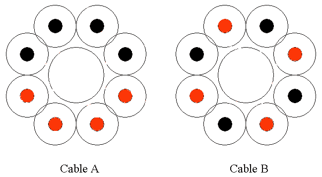
Because the currents are running in the same direction in adjacent conductors in Cable A, the magnetic fields that couple between the same color conductors cause the inductance of Cable A to increase. Since inductance is an important thing to minimize in speaker cables, this is a bad thing. In Cable B, the conductors are alternated so that adjacent conductors have current running in opposite directions. This tends to reduce the inductance of Cable B, which makes Cable B the superior design.
RF resonances and "pollution"
Some cable manufacturers would have you believe that RF can easily sneak into interconnects, speaker cables and power cords. Here is the reality:
Interconnect Shielding
Even in high-RF urban environments, shielding of interconnects is prudent, but not usually necessary. The shielding need only have coverage such that the shortest wavelength is attenuated by 50 dB or so. If the offending RF is television or radio, the size of the openings in the cable’s shield need only be about ¼" in diameter, which is a very sparse shield. If the offending RF is cell phones and other 800+ MHz RF, then holes in the 1/8" range should be sufficient. Most common shields are much more dense than this, having a minimum of 90% coverage. Shields add capacitance to the interconnect, so they should be used only when absolutely necessary. A 90% coverage shield should be more than adequate for audio interconnects, unless you live next to a transmitter. Most folks can successfully use an unshielded cable, such as Kimber without any audible noise being picked-up.
Interconnect RF Resonances
RF resonances are possible on a shielded cable where the shield is not connected at one end. This has nothing to do with the shield coverage, but with the length of the "stub" antenna that is created by the un-terminated shield. If the length of the un-terminated shield is equal to ½ or ¼ wavelength of a nearby RF transmission, a small AC voltage may develop over the length of the shield. If the component driving the cable has a high enough output impedance, the shield voltage could be induced onto the conductors in the cable, which are a similar in length between the discontinuities of the RCA connectors at each end. To eliminate this possibility, a high-frequency capacitor can bridge the gap at the un-terminated end of the shield, behaving as a short at RF frequencies, but an open circuit at the highest audio frequencies.
Speaker Cable Shielding
Shielding of speaker cables is a waste of money and will probably compromise their performance. Speaker cables are driven by extremely low impedance drivers in the amplifier to a very low impedance speaker load. In this low-impedance environment, coupling of low-level high-frequency magnetic or electrical fields will be miniscule and insignificant. Shielding speaker cable can also cause an adverse performance impact by increasing the capacitance of the cable. Better not to do it.
Power Cord Shielding
Shielding of power cables serves no useful purpose. Shielding will add significant capacitance to the cable with minimal positive benefit. If you really need this, then the shield should be spaced well away from the conductors (large diameter) to minimize capacitance and avoid constraining the magnetic field lines that should couple between the conductors. Empirical testing has shown that standard shielded 14 gauge stranded power cord sounds less dynamic than unshielded 14 gauge stranded cord. The impedance of the electrical system is extremely low and susceptibility to magnetic and RF fields is extremely low for power cables so the benefit is questionable at best.
Use of Ferrites to stop RF
Several companies offer clamp-on and slide-on Ferrites. Some audio manufacturers claim that their Ferrites stop RF currents from being "picked-up" by power cords and other audio analog and digital cables. Ferrites are routinely used on computer internal and external cables to block RF. What is really happening here is that these are blocking radiated emissions from the computer so that the computer will pass FCC and foreign emission standards (CISPR, CSA). Their purpose is NOT to prevent RF from being "picked-up" by the signal wires. In some cases they have been added to internal computer cabling to attenuate radiation as a band-aid after the design is complete. These Ferrites will "round-off" the signal edges, removing much of the high-frequency content. The energy that Ferrites absorb is turned into heat as they are lossy elements.
Ferrites on Interconnects
What happens when you put one of these devices on your interconnect? It adds inductance to the cable causing it to be a low-pass filter (passes only lower frequencies). The problem is: if it is a large ferrite, or the composition is not correct, it can roll-off the high audio frequencies. Bad idea. Better to get a shielded cable if RF is suspected to be a problem. Some very small Ferrite beads, however, can be useful in taming some unshielded cables, such as the Kimber PBJ, but the ferrite should be installed on one conductor, not clamped across both.
Ferrites on Speaker Cables
What happens when Ferrites are installed on speaker cables? This is a more interesting question. Ferrites, with the right composition and size can be helpful for optimizing a speaker/cable/amplifier combination. I would avoid using the large clamp-on Ferrites used for EMI (Electro-Magnetic-Interference), since these generally add too much inductance. The Image Clarifier offered by Empirical Audio is a device that works for audio because the composition and size of the Ferrites is specifically chosen for audio cables. The Ferrite cores should be installed on one wire, not across both wires. The reason that Ferrites can improve the performance of speaker cables lies in their ability to add inductance and loss to the cable. We believe that this inductance reduces the natural resonances in a cable, which we believe can become audible through secondary effects. The ferrite creates a low-pass filter at very high frequency.
Power Filtering and Conditioning
Much attention has been given recently to both power filters and power conditioners. In general, the power line voltage should be sufficiently filtered by the input transformer and filter capacitors in a well-designed audio component so that an AC filter will be of little benefit.
AC Power Filters
Power line filtering may protect a component from damage from a lightening strike (because it contains Thyristors), but in general, power filters will insert inductance in series with the power feed, which may limit transient current when the component needs it. Limiting transient current can become audible by limiting dynamics. This should be audible only with component's with poorly designed power supplies. Unfortunately, many superior audio components have inferior power supplies. These components will likely suffer limited dynamics when a power-line filter is used with them. As far as filtering-out power line noise and distortion, these filters do prevent high-frequency noise voltages from getting to the transformer of the audio component, but the transformer itself usually does a good job of filtering these as well, although some toroidal transformers may pass relatively high frequencies. In this case, any high-frequencies that do get through will be swamped-out by the capacitive filters in the audio component power supply anyway. Extremely little high-frequency noise will actually get to the electronics. This is why the reviews on power filters vary so much. It is very dependent on the design of the filter and the audio component power supply. It is possible that an AC filter could be beneficial if the AC noise is significant in your area, the AC filter does not limit transient currents and your audio component has an inferior power supply.
Active Power Conditioners
Active power conditioners are another matter. These can clean-up even the low-frequency distortion in the power voltage waveform, making the power conversion in the component’s transformer more efficient. They may also change the phase of the current in an optimal way. Reviewers have noted that 80-90 Hz is an improvement over 60 Hz in most audio components. This is probably due to the fact that the losses in the transformer are reduced at higher frequencies or that phase changes in the current make the voltage conversion process less lossy. Alternately, the output voltage from the transformer may actually be increasing, giving the component more headroom, but at the same time shrinking the voltage safety margin for the transistor or tube devices. This can be dangerous for the devices and their reliability. Whichever of these is really at work in a given conditioner, it is clear that they can be beneficial, particularly in the case where the power supply design in the audio component is inferior.